

LED Aluminum Heat Sink Thermal Resistance
Engineering calculation benchmarks for LED heat sinks
Aluminum LED heat sinks designed to handle thermal loads ranging from 100 W to 500 W, with a target thermal resistance from the heat sink to the ambient environment of less than 0.4 °C/W, to keep the solid-state junction temperature below the critical structural degradation threshold of 85 °C. Under natural convection conditions, to prevent thermal boundary layer overlap and achieve this baseline efficiency, the minimum fin spacing is set at 6.5 mm, with an effective heat dissipation area density of 35–45 cm²/W. When the design shifts to a forced convection system (air velocity ≥ 2.0 m/s), the fin spacing must be reduced to 1.8–2.5 mm to maximize the total heat dissipation area, and the substrate thickness must be maintained at a minimum of 6.0 mm to effectively suppress the thermal resistance of high-heat-flux-density LED arrays.
Analysis of Heat Conduction Pathways
The total thermal resistance of a high-power LED is the physical sum of three independent thermal interfaces: the conductive thermal resistance within the package, the contact thermal resistance across the thermal interface material, and the convective thermal resistance from the heat sink to the ambient air.
In designs with high heat flux density (> 15 W/cm²), the primary challenge occurs within the substrate before heat is conducted to the vertical heat sink fins. If the substrate is too thin relative to the LED mounting surface, heat flow will encounter resistance from material contraction during lateral diffusion-known as thermal diffusion resistance. The severity of this resistance is directly related to the difference between the heat sink base area and the heat source area, and is largely determined by the intrinsic thermal conductivity of the aluminum alloy. Excessive local thermal diffusion resistance can create hot spots directly beneath the LED array.
To keep the thermal resistance below 0.05°C/W, high-precision CNC planar machining must ensure that the substrate flatness tolerance is ≤ 0.02 mm per 100 mm linear span, with a surface roughness of Ra 0.8 μm. Precise mechanical alignment can control the thickness of the thermal interface material to within 30 μm, reducing the interfacial contact thermal resistance by up to 40% compared to a standard extruded surface (Ra 3.2 μm).

Engineering Design of Active Convection and Passive Convection Cooling Systems
When designing the geometric parameters of cooling fins, the dimensions of the aerodynamic channel must be matched to the dominant fluid flow conditions. In passive convective cooling environments, airflow velocities rarely exceed 0.3 m/s. If cooling fins are arranged too densely (spacing < 5.0 mm), the relative velocity boundary layers within the channel will interfere and overlap, causing thermal stagnation and obstructing airflow.
In forced convection cooling architectures that use active fans or impellers, the airflow boundary layer is significantly compressed. This allows engineers to increase fin density and raise the aspect ratio to 20:1, substantially increasing the total effective heat dissipation area per unit volume.
|
Engineering Parameter |
Natural Convection Baseline |
Forced Convection (Velocity 2.5 m/s) |
Mechanical Verification & Test Standard |
|---|---|---|---|
|
Optimal Fin Pitch |
6.5mm – 9.0mm |
1.8mm – 3.0mm |
Calibrated Optical Comparator |
|
Fin Thickness |
1.5mm – 2.5mm |
0.8mm – 1.2mm |
Digital Micrometer (± 0.005mm) |
|
Maximum Aspect Ratio |
8:1 |
18:1 to 25:1 |
Extrusion Die Structural Limit |
|
Target Thermal Resistance Range |
0.8°C/W – 2.5°C/W |
0.15°C/W – 0.4°C/W |
Wind Tunnel Thermal Bench |
|
Surface Radiation Contribution |
15% – 25% of Total Dissipation |
< 3% of Total Dissipation |
ASTM E408 Emissivity Testing |

Aluminum Extruded Profile Heat sink Factory in China
To optimize structural integration and thermal performance for complex lighting modules, please contact our R&D engineering team directly to customize specialized extrusion dies for your project through our production line.
Material Selection: AL6063-T5 extruded aluminum profiles offer superior performance compared to other alloys
The choice of material directly determines thermal conductivity and machinability. Although pure copper (C11000) has a higher volumetric thermal conductivity (386 W/m·K), its high density (8.96 g/cm³) and raw material costs completely rule it out for LED housing designs that require lightweight construction.
Among the many aluminum alloys available, extruded AL6063-T5 is the industry standard for high-precision heat sinks. The extrusion process aligns the internal microstructure of grain boundaries parallel to the direction of heat flow, resulting in superior thermal conductivity compared to high-pressure die-cast alloys (such as ADC12, where high internal porosity and a high silicon content hinder lattice heat transfer).
|
Material Alloy |
Thermal Conductivity |
Yield Strength |
Density |
Primary Manufacturing Process |
|---|---|---|---|---|
|
AL6063-T5 |
201 W/m·K |
145 MPa |
2.70 g/cm³ |
Precision Hot Extrusion |
|
AL6061-T6 |
167 W/m·K |
276 MPa |
2.70 g/cm³ |
Extrusion / Structural CNC Machining |
|
ADC12 (A380) |
96 W/m·K |
160 MPa |
2.74 g/cm³ |
High-Pressure Die Casting (HPDC) |
|
AL1050 (Pure Aluminum) |
222 W/m·K |
85 MPa |
2.71 g/cm³ |
Cold Stamping / Skiving |
CNC Machining and Surface Anodizing
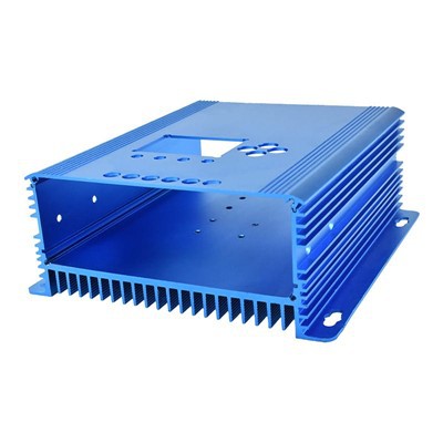
Heat sinks produced by extrusion molding do not have high dimensional accuracy; therefore, the mounting surfaces of LED heat sinks, O-ring grooves, and mounting threads for optical components-which all require high precision-must undergo secondary precision machining. The use of a five-axis CNC machining center ensures that geometric positioning tolerances are strictly controlled within ±0.01 mm, completely eliminating cumulative errors caused by secondary clamping. All mounting reference surfaces are verified using a CMM (coordinate measuring machine).
Surface emissivity (ε) determines a material's ability to dissipate heat through radiation. The surface emissivity of untreated machined parts is only about 0.05. Anodizing the surface and strictly controlling the oxide layer thickness to 15 μm can increase the surface emissivity to 0.85 or higher. This anodized layer can enhance passive radiative cooling capacity by 18%.

FAQ
1. What are the standard CMM inspection specifications for the flatness of LED heat sink substrates?
CMM inspection uses a ruby probe to take samples within a 100 mm² grid area, with a minimum measurement density of 25 measurement points per square inch. This ensures that the absolute contour deviation of the substrate surface is controlled to ≤ 0.02 mm
2. How does the draft angle of extrusion dies for aluminum profiles affect the performance of heat sink fins?
When the height of extruded heat sink fins exceeds 50 mm, the die typically requires a minimum draft angle of 0.5° to 1.0°. Excessive draft angles reduce the cross-sectional area at the tips of the fins, resulting in a 6% decrease in heat transfer efficiency at the distal ends of the fins.
3. What is the production lead time for custom extruded LED heat sink prototypes?
Shipped within 7 to 15 business days after confirmation of the CAD engineering drawings.


